 (510) 868-1614
Installations

A typical installation consists of a small radio that is externally mounted on the roof of your home or somewhere on your property and is designed to receive internet wirelessly from one of our local transmission towers.
Obstacles such as dense foliage or buildings could impact your line of sight so our installers will work to find a location which enables the strongest signal while being as unobtrusive as possible.
An ethernet cable is run from the radio to the inside of your home which will connect to a POE injector (a device that plugs into a power outlet). There is an additional ethernet port on the POE that can be used to plug in your personal computer or router.
In order to properly connect to the internet, your device will need to be programmed with static IP’s. These will be given to you at the time of the installation and also sent via email for your records.
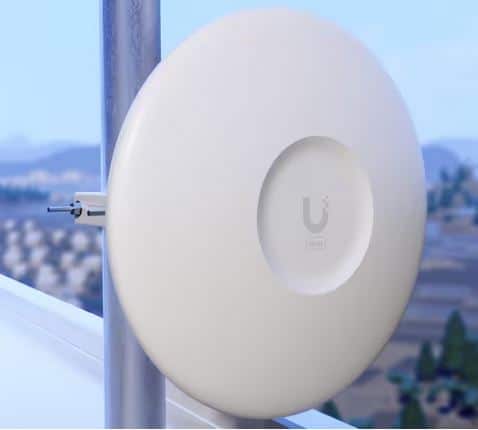
The installer will leverage an existing vent pipe on the roof, if available, for mounting the radio. (As shown in Diagram 1 & 2)
If no pipe is available, the installer will leverage another secure object to mount the reflector (brick chimney, roof eave, etc.), or will drill into the fascia board.
**Special non-penetrating roof sleds can be used if desired. Sleds are placed on a rubber mat and weighted down by six cinder blocks, thus requiring a flat roof for use. (See Diagram 3)
Once the equipment is secure, the installer will run a shielded cat5 cable into the building leveraging a pre-existing hole or vent. If such a pre-existing hole does not exist, the installer will need to drill a new hole for the cables, which will then be sealed to avoid any potential water leaks.
The Cat5 cable will enter the customer’s premise and connect to a Ubiquiti power injector which will be plugged into a standard AC wall outlet or surge-protected power strip (desired).
If you would like any more information on the Ubiquiti products we use, you can view the individual datasheets at the following links: LTU-LR (Diagram 1) and Wave Radio (Diagram 2)